AIO
How to Build an All-In-One Workstation.

Truly Portable DIY AiO
DIY Project to build a portable All-in-One from scratch.
This is an in-house project to build a fully functional truly portable All-in-One PCs by our various teams. The goal is to completely experience the truly portable All-in-One form factor before our golden sample becomes available. Using this new form factor for real in different teams will inform us on fine tuning details on our ViCase-Stand design befor taping it out to production. This is a fully functionl All-in-One PC design with the unique feature of being truly portable. We shared it here in case someone finds it useful. You can give feedback or request features by pressing the flow button and open the Article Issue, then simply post us a comment.
Get involved: edit Article, report issues and ideas, see what we are working on in GitHub. Read → More
Table of Contents
Introduction
Portable AiO Magic
Quick To Change Location: We wanted to be able to quickly change where we work. Once you have the freedom to do so you will be surprised how often you actually want to: Be it to quickly switch who to work with, or to work on the balcony on a sunny day, and more …
Full Desktop: We could have used a Laptop. But we wanted a full desktop with all its benefits, such as higher value for money, easier upgradeability, longer service life, higher performance.
Big Screen: The big 28” screen of an All-in-One is simply a more productive tool than the small 13” screen of a laptop.
Clean Desk: This is a mere side effect, but one we love all the same: Our desk looks much cleaner!
Personal Favorites:
- Me: Work side by side with team member. I switch location each time I switch team. Several times a day.
- Son: Use the computer in the bed placed on his drawing board. Way more fun than his tablet :-)
- Wife: Bring her PC to the kitchen when cooking to chat with friends and watch movies.
How quick is it?
In under one minute you could relocate from a to b, e.g. from the work room to the balcony and be working again:
- You get the urge to work in another place.
- Smile, simply stop working, and hibernate you PC.
- Place mouse and keyboard into keyboard shelf.
- Unplug the power cable.
- Grab your workstation and carry it from a to b.
- Plug in the power cable.
- Wake up your PC and take out mouse and keyboard from the shelf.
- Continue working with a smile.
Note: This setup is not light. Depending on screen size and wood type you end up with a 5 … 10 kg unit. However, you typically would carry it for under one minute and as such it is fine. This is not a rig for traveling! Instead ViCase + ViCase-Stand is designed for traveling and is made compatible with on board luggage constraints of airlines.
3 Tricks
- Hibernation & Resume : Instantly freeze your computer. Move to a new location. Resume where you left off.
- Single Cable Only: Only one cable to unplug before you move. Only one cable to plug in. Simply. Fast.
- Everything on the Grip: Grab you workstation and go! No packaging, no cable organizing. Just go!
Features
Key Features
- Elegant
- Portable
- Practical
- Organized
- Full Desktop
- GPU Support
- Integrated
- Modular Big Screen
Feature Slideshow
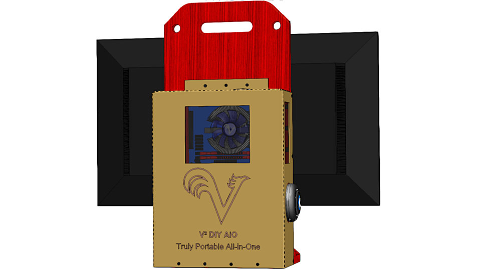
Simple & Elegant
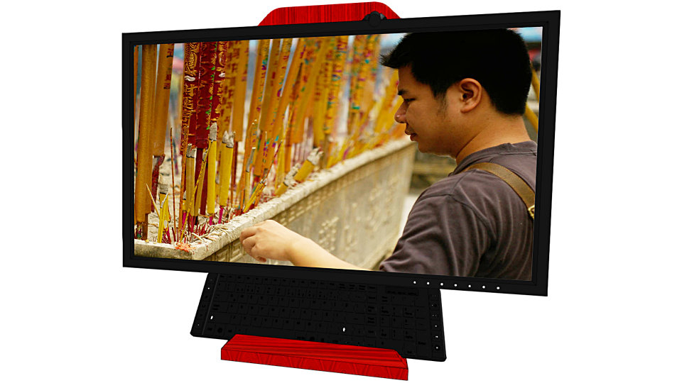
This is front view of the DIY All-in-One with the keyboard placed in the shelf.
Grip

I used the very first Mac which came with a carry grip. I have missed the grip ever since on all my subsequent computers. This one is placed in the center of gravity with a nice smooth shape to not cut into your fingers.
Carrying via Hand Grip
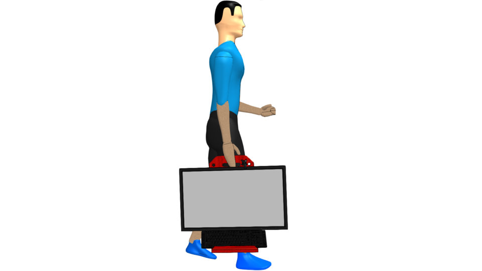
The carry grip is sufficient for short distances, say from your work room to the living room. For reference, this is a 1.8 m tall person carrying an All-in-One with 28” display.
Carrying via Shoulder Strap
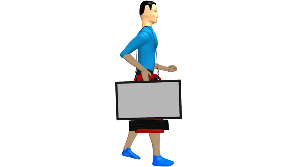
You can use a shoulder strap for longer walks.
Single Cable Connection
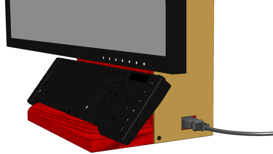
Changing your location is so fast, because you only need to handle this one power cable.
Microphone & Speaker

Placement of your speaker and microphone behind your display. They are connected with cables through the cable break outs as shown below.
Shelf for Mouse & Utensils

The integrated shelf can carry your mouse, pens, eraser, and so forth.
Keyboard in Shelf
It also fits a full size keyboard, keeping your desk free for other tasks or stores your keyboard when carrying your workstation. And cat owners will find their PC still sleeping in the morning :-).
Quiet Airflow
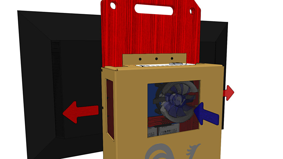
The CPU cooler sucks in cold air (blue arrow), leading to very efficient and quiet cooling. The hot air exhausts through the two grills on the side (red arrow). This is a simple airflow, yet more efficient and quiet than that of common desktop cases.
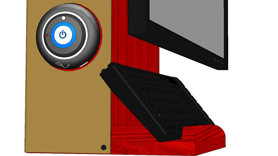
Power On, Status LED & USB

The round thing is where you power on / off your PC, check its status LEDs or plug in other temporary USB devices.
Headset Hook
When not in use this hook keeps your headset of your desk.
Display Tilt

You can adjust the display tilt at the time when you mount your display.
Easy Access to IO
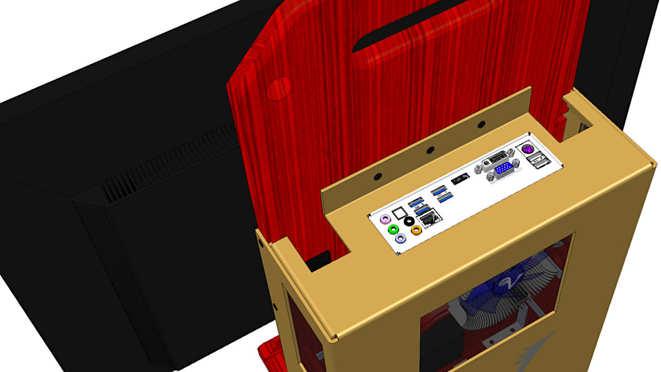
We placed the IO panel facing upwards. This gives you easy access to it. Yet cable mess is reduced to a minimum as all cables can enter into the two holes left and right to the IO panel.
Hidden Cables
All cables are inside the cover and hidden from sight. This gets cables out of the way when carrying your workstation and also keeps the cosmetic appearance clean.
Making
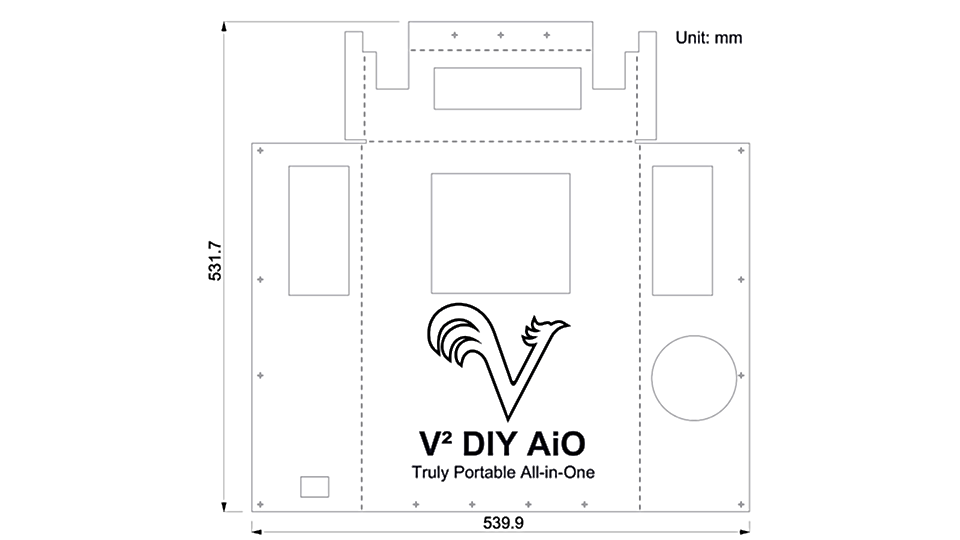
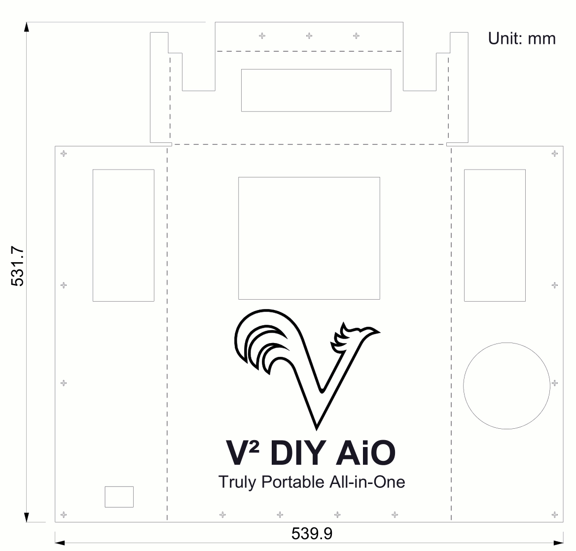
Drawings
Schematics

| SVG | PNG | DXF | |
|---|---|---|---|
| Schematic | Schematic | Schematic | Schematic |
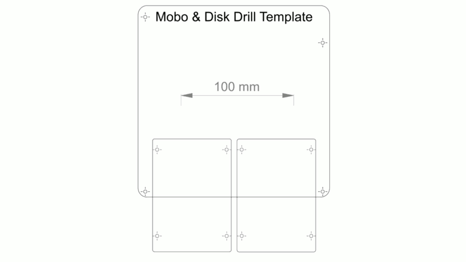
Mobo & Disk Drill Template
| SVG | PNG |
|---|---|
| Drill Template | Drill Template |
Laser Cut Cover
| SVG | PNG | DXF | |
|---|---|---|---|
| Cover | Cover | Cover | Cover |
Call Outs
| # | Name | Function |
|---|---|---|
| 1 | Nice Corner | 45° cut with hand saw, smooth corners with file and sand paper. |
| 2 | Hand Grip | Drill two 25 Ø mm holes, cut connection with hand saw, smooth inside with wood file and sand paper. |
| 3 | Strap Hole | Drill 20 mm holes. Deburr with sand paper. Connect shoulder strap with carabiner. |
| 4 | VESA Wall Mount | Connects Display to Base Board. Align top of VESA mount with top of motherboard. Drill from mounting side. Use M5 metal screws |
| 5 | Mini ITX | PC Motherboard. Drill holes using drill template. Drill from mounting side. Use M3 screws plus 20 mm female-female brass spacer. |
| 6 | Cable Break Out | Especially for Display Power and Display Signal Cables. Drill 10 mm hole with center 10 mm of edge. Cut open with hand saw. Deburr with sand paper. |
| 7 | 2.5” Disks | Drill 4 mm Ø holes using drill template. Drill from mounting side. Fix drives with M3. Use rubber grommets between Back-Board and disks. |
| 8 | Grain | Direction of Grain. Choose your wood so that its grain direction is identical to the one in this schematic. |
| 9 | Back Board | Holding Display, Motherboard, Disks, Power Supply. 1” nominal wood as in 3/4” real thickness. Equivalent 19 mm. |
| 10 | Placement Left | Where to place Left-Side-Board onto Base-Board. |
| 11 | Placement Right | Where to place Right-Side-Board onto Base-Board. |
| 12 | Placement Back | Where to place Back-Side-Board onto Base-Board. |
| 13 | Base Board | Base / Foot of case |
| 14 | Cable Exit Thingy | 20 mm Ø hole for cable of the Power On / Status LED / USB Port thingy. |
| 15 | Left Side Board | Connects Base Board to Back Board |
| 16 | Right Side Board | Connects Base Board to Back Board |
| 17 | Socket of Y-Cable | C14 Socket of AC Y Cable. (We did not draw the cable) |
Cutting
- Total need to cut 4 pcs. Big cuts can be made in home depot or equivalent shop.
- Pay attention to the direction of the grain. It is marked in the drawing.
- Corner cuts are 45° made with hand saw.
Drilling
Drill Templates
Using the Drill Template for Mobo & Disk
- Print the templates 1:1. You may need to adjust your print settings to do so.
- Verify Scale: Check with a ruler if the 100 mm marks are really 100 mm apart. If not, then you need to adjust your print settings and print again until you have a true to scale print. This is important so that your drill holes that match the mounting holes of your devices. Another way to check is to place your motherboard onto the template. The outline and drill holes must match up!
- Place in final position: The drill template shows the parts in true to scale size. Place your drill template so that the parts are in the final position you want. Fix it with tape. You can mark your hole position with the respective marking tool or you can simply drill through the template and toss it afterwards.
- Use waste board: You need to drill through. Place a board you do not care about under your work sheet. This way you drill into that one and not your beloved table.
- Drill from mounting side: Depending your skill and whether you are using a drill press or not your holes will be more or less orthogonal. This will be less of a problem in terms of your drill holes match up with the position of your mounting holes if you drill from the mounting side.
- De-burr: Use a 10 mm HSS metal drill bit with your hand to cut off any burrs. Especially on your drill exit side.
Power Supplies
- Place the power supplies onto the back board into their final position
- Mark the drill holes with the awl
- Remove the power supplies and drill 2 mm holes about 10 mm deep
Hand Grip
- Mark the Center Holes
- Use the 25 mm bit to drill the holes
- Use the wood saw to cut the connection between the two holes
- Smooth the inside edges with the wood file
- Repeat the process with sand paper. Start with 90, then 180, then 360, then 600 until smooth
VESA Bracket
- Place the VESA bracket onto the front side of the Back Board.
- Align top edge of the VESA bracket to the connecting line between the top motherboard screw holes
- Center the bracket
- Mark holes with awl
- Drill holes from the mounting side 5 mm Ø
- De-burr from both sides
Painting
This is the joy of DIY. Express yourself. Like to have a natural Oak computer. This is your chance. Or you prefer a screaming red punk version? Or simply black? After you cut, drilled, and sanded your wood parts you can paint them any color you want. If you choose a solid color then first apply wood filler. Sand thereafter and apply the solid color, polish with a fine sand grain like 1000, spray paint again, polish again and finally apply a spray lacquer.
Assembly
Mounting Side Board

- Place first Side Board on Base Board. Fix it with 2 L-brackets. Each L-brackets use 4 pcs of 4 mm Ø wood screws, pan head, 15 mm long.
- Repeat process for second Side Board.
- Repeat Process for Back Board. Back board is connected with two L-brackets each to the Left Side, Base Board and Right Side
Wiring
Mounting AC Cable Socket
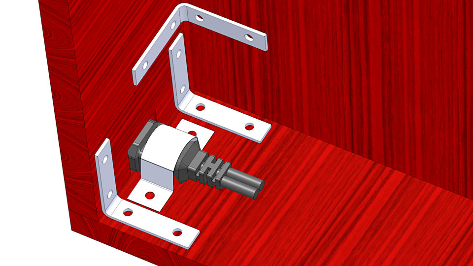
Our solution to mount the AC Y-Cable is unconventional, yet effective and safe. Use a conduit strap like in the picture above. If you can not find one of the right size you can easily cut one from a used soda can (Coke can).
Overview Placement Electronics
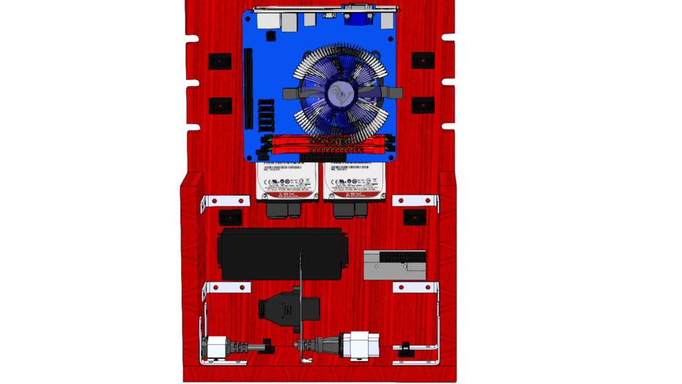
You parts and arrangement may vary. But the idea is always the same. Place the parts where is place and so that the wiring is convenient. Fix the parts with wood screws Ø 4 mm and length of 15 mm. Pre drilling is not needed.
Detail Placement Electronics
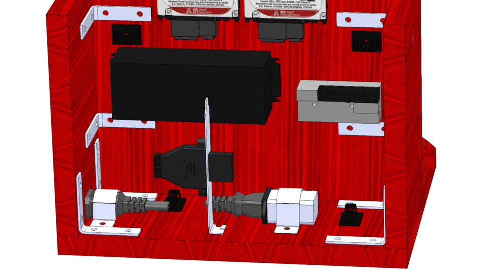
A more detailed view.
DC GND Wiring
Actual Wiring
The Grounding cable of the HDPLEX AC-DC PSU is screwed in between two 10 mm Brass spacer. One spacer is male-female, other space is male-male. Ring terminal goes in between their mating.
How DC GND is Connected to AC Earth
- ATX cable of DC-DC PSU plugs into motherboard and connects DC GND of PSU to DC GND of motherboard
- DC Ground of motherboard is connected to mounting holes of motherboard
- Motherboard is connected with M3 screws to spacer, one of which is connected to GND of AC-DC PSU
- AC-DC PSU earth wire should be connected to AC Earth prong of the AC cable
- The Earth prong of the AC power outlet is connected to Ground, as in hammer a steel pole into the ground.
- All connector shells of the motherboard are connected to DGND of the motherboard. Thanks to our wiring it is connected to Earth which will assist in dissipating Electro Static Discharges (ESD) and thus avoid crashes of your commuter or premature aging of computer parts.
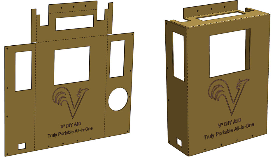
Cover
Shopping
Shopping Mechanicals
- Wood Shelving / Common Board Pin Wood actual 0.75” x 11.25 (minimum 4 feet long)
- Brass Spacer, threaded M3, hex shape, height 25 mm or 1 inch
- 3/4” quarter round molding
- Nailed on edge of floor board. Prevent keyboard to slide out of the keyboard shelf
- card board, single flute, micro flute, about 3 mm thickness, strong hard paper, maybe 200 gsm or better. Brown or black color. About 3 ft x 3 ft
- 25 mm Ø wood drill. Type: “Flat Spade” or “Forstner” for hand grip
- 20 mm Ø wood drill. Type: “Flat Spade” or “Forstner” for AC Socket
- VESA Wall Mount. → Luxury ViCase-Stand #126
- pick one that has 4 mounting holes to the wall. 2 will not be enough using wood screws.
- Cable Ties that can open many times. Screwed to base board
- Either same type as we used in ViCase / ViCase-Stand
- Wood screws plus copper wire 0.8 mm, single strand
- Wood paste
- Lacquer Spray Can, fast dry, red (Choose color to your taste. Red may go well with cardboard brown)
- Lacquer Spray Can, fast dry, transparent
- Black Grill / Mosquito Net
Shopping Electronics
- 1 x Intel i3 6100 $125
- 1 x Asus B150 Mini ITX WiFi $125
- 2 x Kingston 4 GB DDR4 memory $54
- 1 x Samsung 850 EVO 250 GB $92
- Windows 10
- 1 x Brass Spacer, threaded M3, hex shape, height 25 mm or 1 inch
- 1 x HDPLEX 160W AC-DC Power Supply $55
- 1 x HDPLEX 160W DC-DC Power Supply $35
- 1 x C14 - C13 Y Splitter $7
- 1 x Computer Extension Cord C14 C13 4ft $3
- 1 set Spacer / Screw Assortment $12
- 1 set Adjustable Cable Holder
- 1 x Power Switch & Status LEDs
- 1 x Speaker Bar
- 1 x Goose Neck Microphone
Parts you may have
- HSS Metal Drill Bits:
- 1.5 mm Ø (drill holes in hard wood profile for thin nails to avoid splicing the wood)
- 3 mm Ø (drill holes for M3 screws, core holes for W5 screws to avoid splicing wood)
- 5 mm Ø (Drill holes in Base Board and Back Board to connect with W5 screws )
- Countersunk Drill Bit
- Small wood nails. About 1.5 mm Ø, about 20 mm long
- To nail the hard wood profile to the foot board
- Rubber Grommet, 3 mm interior Ø ( we will find on amazon, optional)
- M3 Screws, Pan Head, PH2 or PZ 2 drive
- 10 mm (Mounting Motherboard to Brass Spacer)
- 25 mm (for HDD in case above not long enough and for mounting Spacer)
- 30 mm (in case the wood was thicker than anticipated)
- M4 x 10 mm, Pan Head, PH2 or PZ2, (for mounting VESA bracket to Display)
- M3 washer, to shorten the M3 screws for HDD without actually cutting them
- Wood screws, 5 mm Ø, countersunk, PH2 or PZ2
- 20 mm (thin bracket material with countersunk hole), (mount VESA Bracket to Base Board)
- 25 mm (in case of bracket to be of thicker material)
- 40 mm (Connecting Boards: 1) Base to Side 2) Side to Back
- Wood screws, 4 mm Ø, Pan Head or better Flat Head, PH2 or PZ2, black
- 10 mm (screw card board housing to base board)
- Wood file
- Sand paper: 90, 180, 360, 600
- try to find linen based versus paper based, not critical but better for sanding hand grip.
- Wood glue
- Wood filler / wood paste
Learning for ViCase-Stand
Confirmed Change List
Headset Holder: Proofed very useful. We are adding one to the current ViCase-Stand design. The idea is to use the same snap fit mounting mechanism as for the foot.
Display Tilt: Allows for tilt adjustment during use.
Shoulder Strap: We are adding holes for it. They are close to edge so there is no need to use a carabiner.
Mounting ViCase Access: We will add a simple solution. Need to be snap fit or magnetic fit now considering the new quick assembly paradigm.
Weight saving design: Cut out material that we do not need to save weight.
Microphone Connection: Find a microphone that can be mounted with a screw. Add a screw insert to hold the microphone.
Loudspeaker: We need to see how to design it in. No idea yet. Can we find a speaker bar that can be glued to the Display? Or small enough so we can screw it to the Back-Board of ViCase-Stand?
Cable Cover: Covering all cable improved the cosmetics. Current ViCase-Stand design cleans up the cables but leaves them out in the open. We are now adding an optional cable cover. It is a laser cut plastic cover that snap fits over the cable management area. Sold as optional accessory.
Mouse & Accessory Holder: Black plastic box with double faced tape to be glued to back of display. Sold as optional accessory.
Features to Discuss
Shelf Bottom: Using V² DIY AiO will show if we need it or not. Current ViCase-Stand design has no shelf bottom. Is that acceptable? Should we offer an accessory of a pencil holder that is glued with double faced tape behind display?
Awaited Learning
Portable Solidworks Workstation: We are getting ready to visit factories for ViCase production. A portable Solidworks Workstation is a big help. This is an interesting additional early sample experience further informing design details for real world use for ViCase.
Misc Learning
Lasercut Cardboard
Will this be an efficient way to quickly and with low cost make custom product and shipping boxes?
Referral Income
We figured out a second revenue income stream for V²: Put our DIY articles on Instructables and add shopping lists including links to amazon and newegg using their referral system so to earn the referral fee on a joint checking account. We can split income according to ratio of work invested.
New way to get traffic
Articles on Instructables should also bring us traffic to the web site. It is one more avenue for the Publisher of a V²Article to create traffic for it.
Reference
- https://en.wikipedia.org/wiki/IEC_60320#C14
Modal title
Hi
Lorem ipsum dolor sit amet, consectetur adipiscing elit. Vivamus non laoreet odio, vitae placerat mi. Maecenas dictum, ex vitae sodales finibus, magna ante aliquam magna, in congue tortor lacus ac arcu. Vivamus semper aliquam bibendum. Nulla a eleifend diam. Mauris porttitor velit ac ante tincidunt, cursus volutpat ligula vulputate. Nam tincidunt tortor sit amet odio scelerisque molestie at a odio. Lorem ipsum dolor sit amet, consectetur adipiscing elit.
Bye
Aliquam posuere arcu libero, quis congue leo ultrices in. Proin euismod rutrum urna sit amet ullamcorper. Integer aliquam diam eu gravida elementum. Fusce bibendum posuere augue, at sagittis enim accumsan in. Mauris luctus massa vel nunc ullamcorper, ut viverra justo sagittis. Vestibulum et felis fringilla, blandit augue a, facilisis magna. Aliquam ut nulla nisi. Donec ut arcu rhoncus, pellentesque nisl pellentesque, scelerisque odio. Fusce nec leo in elit molestie fermentum et et lorem. Maecenas venenatis hendrerit metus, sed volutpat lorem luctus in. Aliquam fermentum ac urna in blandit.