Flow
Workflows on contributing to V² in ready to use quality.
Workflow from CAD to CAM to CNC
Workflow and Tutorial to turn your CAD design into a CNC cut part you can hold in your hands.
Creating the CNC files that you feed to the CNC machine is not nearly as clear cut as you would expect. (Pun intended). Instead it is a creative process similar to creating the CAD file of your design. As always many ways lead to Rome (or Beijing apparently) and your mileage will vary. That being said, following this guide you will find Rome. You will get their with no detours. And you will get there in time yet travelling economy class.
Get involved: edit Article, report issues and ideas, see what we are working on in GitHub. Read → More
Table of Contents
Overview
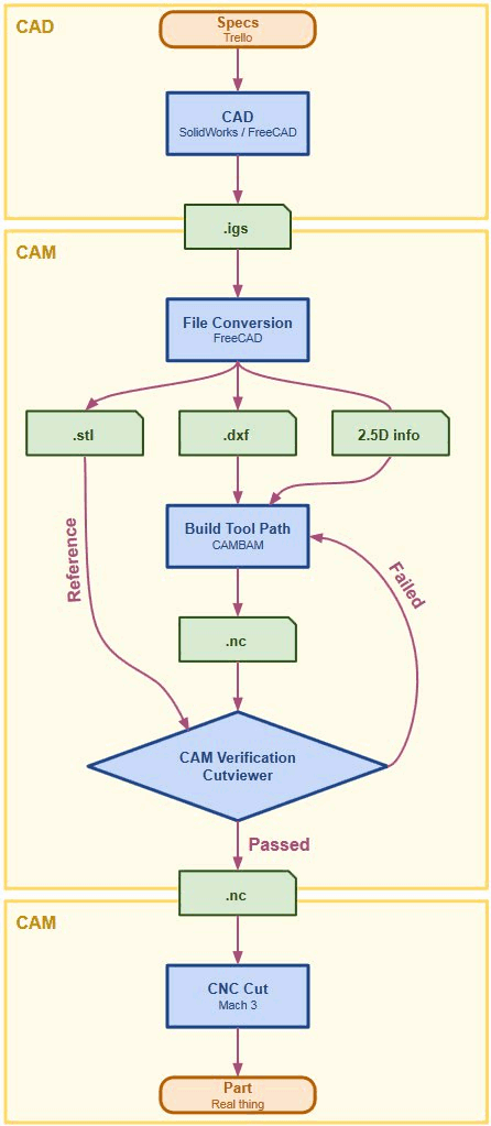
Specs Specifications and to do lists to complete the design. We use GitHub and Trello to organize, coordinate, delegate and synchronize our work.
CAD: We design the part or a complete assembly of parts in Computer Aided Design. We use SolidWorks for complex designs such as ViCase and FreeCAD for simple designs, such as Fixtures to help manufacturing, say assembling ViCase.
.igs File: This file format works well to transfer the design of one part from CAD → CAM.
File Conversion: The CAM department uses FreeCAM to convert the .igs files into .stl and .dxf files plus 3D info.
CAM: The CAM (Computer Aided Manufacturing) process generates Tool Paths saved in a .nc (numeric control) file. The CNC Machine load the nc file and follows the Tool Paths with its tools and thus cutting everything away which is not needed.
Building Toolpaths: is a complicated job that requires a lot of skill and experience. The CAM engineer exports a feature outline from FreeCAD in .dxf, imports it into Cambam and then adds CNC attributes to it such as feed and spindle speed. Once done the toolpaths are saved in the .nc file.
CAM Verification: Since the generation of Tool Paths is a manual process, errors can happen. The purpose of CAM Verification is to find these Errors before cutting the part in CNC to avoid high costs.
.nc: is the file format we chose to hand over the part as numeric control file from CAM → CNC.
CNC Cut: The process where a Computer Numeric Controlled Machine moves a tool along a tool path, cutting away all stock material which is not needed and revealing the part.
Part: The CNC cut component from which we build our product case.
File Conversions
Export IGS from SolidWorks to FreeCAD
We make all our mechanical CAD design and design verification in SolidWorks. When complete we hand over the CAD design to the CAM department. The CAM department uses FreeCAD instead of SolidWorks for a number of reasons:
- Faster learning curve for beginners
- FreeCAD does everything we need it to do in the CAM department at zero cost
- We plan to release the CAD file to the Open Source CNC and 3D printing community. They use FreeCAD. By including FreeCAD in our workflow we can be sure by the time we release the files they are completely usable in FreeCAD.
FreeCAD Exporting & Reference
From FreeCAD we export to:
- .stl as reference file to compare the part described with the .nc file versus the part described with .stl file
- .dxf imported in Cambam to generate the Tool Paths
FreeCAD will also be needed as constant reference to extract the 3D information. This is a manual process and is required since dxf files are for 2D only and do not contain any third axis information.
Intro to Building Tool Paths in Cambam
Why we choose Cambam
Please see → Choosing CAM Softare
Understanding 2.5D
2.5D is a term used in the CAD-CAM-CNC workflow to describe parts that comply to the following restrictions:
- All shapes are orthogonal exrtrusions of 2 D outline
- As consequence they can be cut with a 3-Axis CNC machine.
- As consequence a 2.5D CAM application can convert 2D outlines to 3D pockets
Paths generated from DXF outlines
For traditional reasons most CAM software will generate tool paths from outlines in DXF files. We use Cambam and it is no different. In the example below it is shown in more detail how that works:
Cutting out a Part
Say you want to cut out a shape from a sheet material with a 6 mm tool. You will do like so:
- Select the shape in FreeCAD and export it as DXF
- Import the DXF file in Cambam. Then convert it to a tool path.
- Expand the shape to be large by the radius of the tool. In this case by 3 mm.
- Add the tool parameter to the tool path, such as dive in depth, feed, spindle speed
Strategies of Chip Removal
When creating the tool path not only the geometry of the final part need to be considered, but also the geometry that is created in the interim.
Strategies for long tool life
Simple but Bad
A simple strategy to automatically generate pockets is to use a low dive in depth, start in the center and then create expanding spirals until reach the outline. Then repeat. Each time dive in for say 1 mm. This method is save and easy to generate, but has two major drawbacks:
- Long machine time (read expensive per part)
- Short tool life (You only use the tip of the tool, so it uses up quickly)
Complicated but Good
A much more efficient strategy is to create two pockets cut with two different strategies:
- Dive in Pocket: Cut with the above strategy. The dive in pocket is as small as possible but as big as necessary to remove all chips when cuttin with the fill depth of the pocket. A rule of thumb is 300% of the tool diameter.
- Fast Cut Pocket: The rest of the pocket is cut with the tool dive in as deep as the pocket is. This way you use the whole tool and not just the tip. Thanks to the Dive in Pocket the chips can be removed without getting stuck, which would break the tool.
Collisions
When the tool is moved outside the workpiece the machine can move with maximum feed speed. But if the tool is cutting the workpiece the feed speed need to be significantly slower. If by accident a tool path is created that brings the tool through material of the workpiece when traveling at high feed the tool will break. This is called a collision. During the design the CAM engineer need to use great care to not design a collision. During CAM verification the CAM designer need to watch out to detect collisions in the CAM verification process.
Pockets
Pockets work similar to → Cutting out a Part, but with three major differences:
- You cut on the inside of the path. As such you need to shrink the shape by the tool’s radius rather than expanding it.
- You do not cut through the material. As such you not only need to generate a tool path along the outline, but also you need to generate additional tool paths to remove all material withing the pocket. As such pockets take much longer to cut and thus are expensive. Whenever possible the design should avoid pockets.
- Due to the more complex tool path more needs to be considered when generating them. See below:
Strategies for long tool life
As the tool path to cut pockets is complex, you can generate it many different ways. Some will cut fast and have a long tool life, some will cut slow with a shortened tool life. Please read more → Strategies for long tool life
Holding Tabs
Purpose
Holding tabs are used in a panel form for two reasons:
- Place more than one workpiece into one sheet for reason of handling efficiency
- Ensure that after cutting a part free (as in separating it from the sheet) it can not move and collide with the tool. This would either break the tool or create unwanted marks in the outline of the part.
Automatic Generation
Cambam provides a feature to design custom holding tabs. Place them in the panel form and then let Cambam worry about generating the tool paths in such a way so that the workpiece has holding tabs when finished.
Rough Cut versus Fine Cut
Rough Cut
When the machine is moving with maximum cut dive in, maximum cut depth, maximum spindle speed and maximum feed it is working at maximum efficiency. Unfortunately the resulting cut surface is more rough. This is OK for most surfaces.
Fine Cut
Surfaces that need to appear smooth to the touch or which need to have low surface roughness or high tolerances need to be cut with a fine cut. This is done with a two step process:
- Rough Cut: Efficient cut, but rough surface. The toolpath is designed as to leave a little too much material after the rough cut.
- Find Cut: The cut depth is reduced to only 0.2 mm. This results into a smoother surface. The fine cut provides the final dimensions.
CAM Quality
The → Intro to Building Tool Paths in Cambam shows that generating the CAM file is not an automated process, but it is — just like CAD — and art. As such different engineers with different experience will produce wastly different NC files. They will differ in cutting time (read cost per part) and quality of surface finish. Let alone the possibility of missing features of features in the wrong place.
As such managing quality of the NC file is a very essential component in managing the quality of CNC production. This is subject to a separate article: Managing CNC Quality in China.
CAM Verification
List of Problems to be found
- Missing feature
- Feature in the wrong place
- Wrong cut depth of the feature
- Tool Collision
- Forgotten Fine Cut
- Inefficient pocket tool path
- Chips can not be removed
How to find CAM problems
We use Cutviewer for the CAM Verification Process. The web site of CutViewer gives a good introduction on the principles. The detailed process on how we use it is shown in a separate Article. This is a topic of a separate article
NC File Generation
NC stands for Numeric Control. Another common term used is GCode or G-Code. Unfortunately the file format is not standardized. Each CNC machine has its own dialect. As such Cambam offers a NC Post Processor to translate the generic G-Code into the specific one needed for the CNC machine operated in the CNC shop. The CNC Shop need to tell you which one they want.
CNC Cut Process
The NC file is loaded into a CNC controller. We use MACH3 for our in-house CNC. The CNC shop may use a different CNC controller. However the function is as following:
- The machinist read the NC file provided
- Most controllers have NC pre processors. They can import many different NC file dialects and then save them in their preferred dialect.
- Most controller have decent CNC similation. The CNC machinist will run the simulation to catch any problem prior to cutting. Problems that slip through may damage the tool, the workpiece or even the machine.
- The machinist will make adjustments. Mostly spindle speed and feed. But they could be more elaborate.
- The machinist places the workpiece on the machine and runs the NC code. Ideally after that you have perfect part in hand.
The whole process is of course more complex. But for the purpose of working together with the CNC shop this understanding is sufficient.
QC of Finished Part
- Critical dimensions are check with caliper
- In mass production we will manufacture gauges to semit automatically check dimensions
- Before mass production we will assemble all parts and check that all works
Panel form separation
- We use a special design of holding tabs that work in concunctino with special panel form spearation tools.
- Some parts need to be separated before going to sand blasting and anodizing for various production reasons
- Some parts can remain in the panel form to reduce handling cost in sanblasting and anodizing process.
Optimizing the NC File
It is likely that the CNC Machinist makes changes to the G-Code file. These can include straight forward changes, such as changing feed and spindle speed. These changes leave the tool paths generated by us intact. But there also could be more elaborate modifications, such as using different tool paths altogether.
After a successful CNC production the CNC shop releases the modified G-Code to use. We analyze it for changes. Any improvements will be transferred both into our workflow and into the updated versino of the G-Code file that we will hand out to the CNC shop on the next production run.
Prepared for Open Source
Goiung Open Source
In the future we will release all ViCase CAD, CAM and CNC files to the Open Source Community. We choose all software applications and file formats to be compatible with defacto standards in the Open Source CNC and 3D Printing community:
CAD: STL & FreeCAD
As for CAD files STL has been established in this community. It is the common format to transfer CAD files for 3D printing and CNC cut. We are hosting our files on GitHub. GitHub even offers build in STL viewer including a STL Diff-Viewer that visually shows differences between two STL file versions:

For more information → GitHub > 3D File Viewer. For this reason we choose our fileformat within the CAD-CAM-CNC workflow to be STL.
FreeCAD is the CAD application used in the community. That is why we build our CAD-CAM-CNC workflow on FreeCAD.
CAM: Cambam & Cutviewer
These are defacto standards in the CNC community. They cost a few hundred USD but in turn they work very well for our purpose. There are Free and Open Source apps available for this job. We tried them and found that they are not ready yet to be used in production. For more details → Choosing CAM Software
Modal title
Hi
Lorem ipsum dolor sit amet, consectetur adipiscing elit. Vivamus non laoreet odio, vitae placerat mi. Maecenas dictum, ex vitae sodales finibus, magna ante aliquam magna, in congue tortor lacus ac arcu. Vivamus semper aliquam bibendum. Nulla a eleifend diam. Mauris porttitor velit ac ante tincidunt, cursus volutpat ligula vulputate. Nam tincidunt tortor sit amet odio scelerisque molestie at a odio. Lorem ipsum dolor sit amet, consectetur adipiscing elit.
Bye
Aliquam posuere arcu libero, quis congue leo ultrices in. Proin euismod rutrum urna sit amet ullamcorper. Integer aliquam diam eu gravida elementum. Fusce bibendum posuere augue, at sagittis enim accumsan in. Mauris luctus massa vel nunc ullamcorper, ut viverra justo sagittis. Vestibulum et felis fringilla, blandit augue a, facilisis magna. Aliquam ut nulla nisi. Donec ut arcu rhoncus, pellentesque nisl pellentesque, scelerisque odio. Fusce nec leo in elit molestie fermentum et et lorem. Maecenas venenatis hendrerit metus, sed volutpat lorem luctus in. Aliquam fermentum ac urna in blandit.